A classification yard is the key feature of the layout design. I have done a lot of research, see here, and have designed the first version according to Craig’s criteria.
Version 1
The initial design, focussing on the classification part in below (the squares in the diagrams on this page are 1 foot by 1 foot).
The lowest two tracks are hmailline. ABove them on the left is the yard lead and off it it the caboose track.
Above the mainline on the right and over to the middle are the Arrival/Departure (A/D) tracks; nominally one for Northbound and one for Southboand trains. Above the A/D tracks are four single ended classification tracks. At the top left is the first stab at an engine service area.
Version 2
The next design tweaked the lengths to better fit the available space, as well as added a hypothetical chemical plant at the back and a turntable and engine shed in the engine service area.
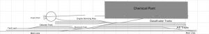
The changes here are a more detailed engine servicing yard with engine shed and turntable, as well as the initial footprint for a chemical plant attached to the yard. I have also shortened some of the lines to better fit the available place. There is a realistic limit of 16 feet to the yard itself.
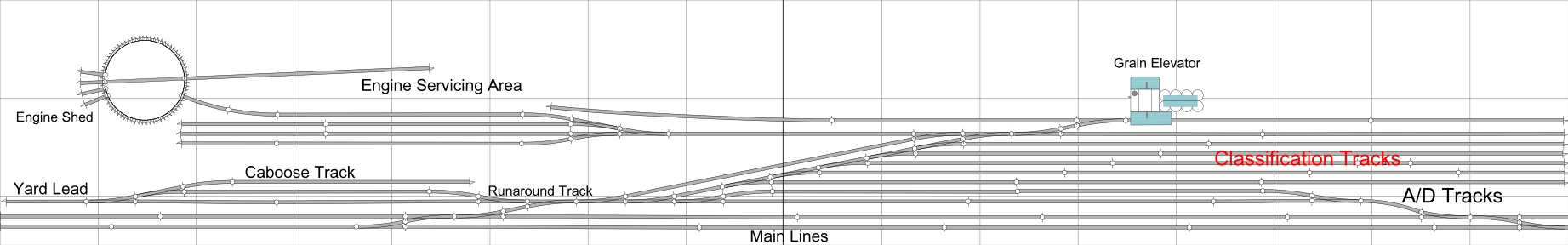
Version 3
Here I decided to shelve the chemical plant. Chemical plants tend to be very large and making a small version would require a lot of research to make it credible. This version replaces it with a grain elevator silo complex based on the Walthers kit. I plan to scratch build additional silos. The track on either side of the silos needs to be 5 feet long to accommodate an entire train (we could maybe make an operational decision to have shorter trains, I will think about that. These tracks would likely be lesser used so that track grass and weathering will allow them to look different than the heavily used main tracks. The classification tracks would be somewhere between, maybe more debris the further away from the main lines. Thie size has been tweaked, it is now 30″ inches wide rather than 3 feet.
Future Changes
For future changes I am thinking:
a) A smaller yard on the other side of the mainline for passenger cars,
b) Additional tweaks to the above features.
c) Design a road-rail interchange area behind the grain silos.
Constraints
The design is more constrained in width than depth just due to the geometry of the switches and my requirement for 800 scale foot trains (real world length, 5 feet). Version 2 has a depth of ~ 3 feet, I have probably another foot of depth available for additional yard and industry space beyond that. Further design will likely be made when I can actually get to construct this yard in real life.